5. Influence of Initial Stress Distribution in Zone of Earthquake
Preparation to Tsunami Formation
5.1. Analysis of Initial Stress Distribution in Seismic Source

|
|
Figure 14
|

|
|
Figure 15
|

|
|
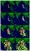
Figure 16
|
[23] The distribution of initial stresses can affect the character of the motion in
the vicinity of a seismic source. It can be demonstrated by the example of the
plain-strain problem for the keyboard model (Figure 2). The material of keyboard
block as well as moving and frontal plates is considered to be an elastoplastic
medium with given parameters and satisfying the Mohr-Coulomb yield criterion.
The velocity distribution in the bottom of the moving plate (Figure 14a) is dictated
by the slow mantle motion. This velocity is causing the accumulation of elastic
stresses in the system. On the contact of the plate and keyboard block the dry
friction force acts. An earthquake occurs when stresses on a local area of the contact
surface exceed the strength limit and resulting slip (Figure 14b) is accelerating.
Since the dynamic interface friction is less than the static friction, the dynamic
frictional resistance falls sharply and the earthquake occurs. This process depends
on the interseismic time and the level of the initial stresses which were achieved
before the nucleation of the seismic motion and can be highly variable. In the case
of small time of preparation, relatively small shear stresses (Figure 15a), and low
residual friction angle value (e.g. of
8.3o
), the displacements in the earthquake
source (Figure 16a) will be oriented in the direction of the plate movement.
Otherwise, in the case of large time of preparation and the greater level of initial
shear stresses (Figure 15b), the displacements will be oriented in the opposite
direction (Figure 16b).
Though the maximum vertical displacement of the sea
bottom in both cases makes about 5 meters generated tsunami waves will be very
different. In Figure 16 there are presented residual keyboard block displacements.
However, the analysis of dynamics of the transient displacement of a sea bottom
shows that the dynamic component of the vertical displacement can exceed the
residual displacement of the bottom established after the earthquake by the factor

|
|
Figure 17
|
of two. In Figure 17a there are shown the variation of the vertical displacement of
the bottom at the point A (Figure 14b) during an earthquake from its nucleation to.
Corresponding plot of the bottom velocity is shown in Figure 17b. It is obvious
that the proper specialization of magnitude and temporal variation of
displacements and velocities of the sea bottom during an earthquake are critical
in the problem of tsunami wave formation.
5.2. Numerical Simulation of Tsunami Wave Generation,
Propagation and Run-up with Taking into Account the Dynamics in
the Earthquake Source

|
|
Figure 18
|
[24] The results of numerical simulation of tsunami wave generation performed
under sea bottom displacements corresponding to Figure 17a are presented in
Figure 18 and Animation 3 (see online version). We have considered a
hypothetical (model) source which can be attributed to Sumatra segment of 2004
earthquake source. The source size was taken equal to 400 km
 150 km.
It was considered a movement of seismic source as a whole according to Figure 17.
150 km.
It was considered a movement of seismic source as a whole according to Figure 17.
[25] Since it is considered local problem then temporal picture of wave coming
to shoreline will reflect the process of surface water wave formation in seismic
source. It is well seen that if period of bottom oscillations is of the order of
30-40 s (i.e. time of uplift and subsidence of keyboard block is of the order
of 20 s) then such movements can be considered as instant bottom displacements.
Then, because of incompressibility of liquid and hydrostatic pressure the tsunami
source is formed as in the piston model, and the wave height above seismic source
will be that as value of displacement in the source. Second uplift of bottom after
35-40 s gives no possibility for the first front to be formed clearly. As result,
there occurs superposition of two fronts and depending on the source the wave height
will be between 1 m and 2.5 m. Mostly it is a first wave.

|
|
Figure 19
|
[26] Further shake on the bottom leads to appearance of large trough at the water
surface, near 4 m in amplitude. In the Figure 19a it is seen two to three well
expressed wave fronts while in seismic source the process is continued during five
periods (see Figure 17).
[27] The Figure 19a corresponds to process of instant release of elastic stress at the
rupture surface. It occurs as result of sharp decrease of the friction angle (from
20o to
8.2o for given case). If it takes place a transient process and friction
angle is a function of time
f(t) then the effect of this to character of surface
displacements will be changed. The jump is a "rigid reaction", in prolongated
f(t) process the period of sea bottom oscillations will be larger. The increase
of oscillation period in three to five times essentially changes the character
of formation of surface water wave by seismic source.

|
|
Figure 20
|

|
|
Figure 21
|
|
|
Figure 22
|
[28] The space-time picture of behaviour of the wave at the shoreline for given
case (Figure 19b) is essentially distinct from the case with "rigid reaction"
(Figure 19a). In this figure, there are more clearly looked all wave fronts and
it is well seen that as a most is a third wave. In Figure 20 it is well seen
clearly expressed fronts of all waves. Figure 21 presents
a distribution of values of run-up at the beach and run-down from the beach for
moments of maximum run-up ( R max = 4.5 m) and
R min is more than 5 m
in magnitude. Using computation method above proposed it was computed a number
of scenarios of generation and propagation of tsunami wave in Indian Ocean basin
for tsunami 26 December 2004. In Figure 22 it is presented one of version of
computations at which it was considered a seismic source 1400 km long and 150 km
width consisting of 14 blocks with equal length [Hirata et al., 2006.
Three time moments of generation in tsunami source are presented in the figure:
t = 20 s;
t = 2 min 20 s;
t = 4 min 50 s, at which it was taken into
account the initial stress distribution in seismic source for each block, the moments
when tsunami attacks the Sumatra island are:
t = 16 min 30 s;
t = 33 min 10 s;
the moment when tsunami attacks the Thailand is:
t = 1 h 50 min;
further propagation of tsunami to Indian coast and attack to east coast of Sri Lanka at
t = 2 h 30 min.
[29] Thus, analysis of the scenarios of generation of tsunami wave with using of
elastoplastic model of subduction zone permits to explain unexpected nonuniform
distribution of tsunami waves for both near-field and far-field coasts.

Powered by TeXWeb (Win32, v.2.0).